


1. The Short Answer: Three Interfaces, Not One
A ball valve seals at three separate interfaces, and only one of them is the one people talk about:
- Ball to seat. The seal that stops the flow. This is the one that determines whether the valve is bubble-tight, and it is the one this page is about.
- Stem to body. The packing. It seals the hole the stem turns through, and it is where most slow weeping starts.
- Body to bonnet, and body to pipe. Gaskets and flange joints. Out of scope here, but they fail independently and get blamed on the seat.
Rotating the ball ninety degrees does not create the seal. It only brings the bore into or out of alignment with the line. The seal itself is made by a ring of material pressed against the ball, and the whole design of the valve is really about how that pressure is generated and where it is allowed to act.
2. What the Ball Actually Does in Ninety Degrees
The closure member is a sphere with a cylindrical bore through it, mounted so the bore axis is perpendicular to the stem axis. Turn the stem, and the bore turns with it.
- Open. The bore is aligned with the pipe. Flow passes through a passage that is essentially a straight pipe segment, which is why a ball valve has the lowest pressure drop of any isolation valve.
- Part way. The bore is partly masked by the seat. Flow is throttled, but the seat is being cut by the flow at the same time. This is the position ball valves are worst at, and the reason a ball valve should not be used as a control valve.
- Closed. The bore is turned ninety degrees away. The solid spherical surface now sits against the seat ring on both ends, and the seal is whatever the seat can hold.
That is the entire kinematic story, and it is the part every article on the internet already tells you. The engineering question is what happens at the seat during those ninety degrees, and that depends on whether the ball is free to move.
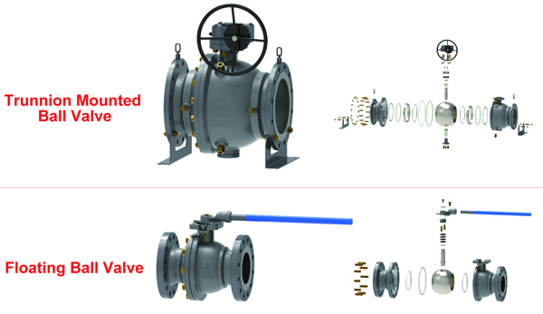
3. Where the Seal Forms: Floating Ball Versus Trunnion
This is the single design decision that changes everything downstream, including torque, size range, pressure class and whether the valve can relieve its own cavity.
| Behaviour | Floating ball | Trunnion mounted ball |
|---|---|---|
| How the ball is supported | Not fixed. Restrained only by the two seat rings | Fixed on a trunnion shaft carried in bearings |
| What line pressure does to the ball | Pushes the whole ball downstream, into the downstream seat | Nothing. The ball cannot move axially |
| Which seat does the sealing | Normally the downstream seat, loaded by the ball | The seat is driven onto the ball by pressure acting on its piston area |
| Seat load source | Differential pressure plus seat preload | Line pressure on the seat back plus spring preload |
| Operating torque | Rises steeply with size and pressure, because the ball is squeezed between seats | Lower and far flatter, because the ball is held by bearings, not by the seats |
| Typical envelope | Smaller sizes and moderate classes; the practical workhorse of general piping | Large sizes and high classes, where a floating ball would need an unreasonable actuator |
| Cavity relief | Inherent. Cavity pressure pushes the ball off the upstream seat, so it bleeds back into the line | Depends entirely on the seat design, covered in the next section |
Two consequences worth spelling out. First, on a floating ball valve the upstream seat is often doing very little sealing while the valve is closed under pressure, because the ball has been pushed away from it; the downstream seat carries the load. Second, on a trunnion valve a single seat failure does not necessarily mean leakage, because the other seat may still be energized. Those are not marketing points, they change how you interpret a seat test result.
4. Seat Logic: Which Side Seals, and Whether It Can Relieve
On a trunnion valve the seat ring is a moving part with a defined pressure-active area, which is why the same valve can be built to seal in one direction or both. The two arrangements behave in opposite ways when pressure comes from inside the body cavity rather than from the line.
| Seat arrangement | Seals from | Cavity pressure does what | Practical consequence |
|---|---|---|---|
| Single piston effect (SPE), also called self-relieving | Line pressure pushes the seat onto the ball | Pushes the seat away from the ball and lets the cavity bleed into the line | Self-protecting in liquid service. Used on both seats this is the DBB configuration. |
| Double piston effect (DPE) | Pressure from either side pushes the seat onto the ball | Pushes the seat harder onto the ball, trapping the cavity | Redundant sealing, but the cavity cannot self-relieve. Used on both seats this is DIB-1. |
| SPE upstream plus DPE downstream | Mixed | Relieves through the upstream seat only | DIB-2. Redundant downstream sealing with automatic relief on one side. |
The naming is worth fixing in your own head, because quotations get it wrong more often than any other clause. DBB means double block and bleed, normally two self-relieving seats. DIB means double isolation and bleed, normally two double-piston seats. A DBB valve can be bled to prove isolation and will also relieve its own cavity. A DIB-1 valve gives you a stronger barrier and hands you the cavity problem to solve yourself.
5. The Cavity Is the Part Nobody Specifies
When the valve is closed, the space between the two seats and the body wall is a sealed volume. In liquid service that volume is full of liquid. Heat it, from sun on the pipe, from a nearby line, or from a fire, and an incompressible fluid in a fixed volume produces a pressure rise that has nothing to do with the pipeline pressure.
This is why cavity relief is written into API 6D as a requirement rather than a recommendation, and why the acceptance limit is stated as a multiple of the rated pressure at 38 Deg C rather than as an absolute number. The commonly cited limit for self-relieving seats is 1.33 times the rated pressure at that temperature; a seat that relieves too early is under-sprung, and one that relieves too late has failed the safety basis.
Practical consequences:
- Liquid service plus DPE seats requires an external relief path. Either a cavity relief valve piped to a safe destination, or a documented alternative. This is the single most common specification gap we see on DIB valves.
- Gas service usually does not need relief on its own account, because gas compresses. It does need it if condensate can form in the cavity, which is common in wet gas and in services that cool down after shutdown.
- A drilled vent hole in the ball is the other route, used on floating designs and in cryogenic service. It is permanent and has no moving parts, but it makes the valve unidirectional, so the flow arrow stops being a suggestion and becomes an installation requirement.
- Ask for the test. A claim of self-relieving seats is a design statement. A cavity relief test, pressurising the cavity with the ends open and recording the pressure at which the seat lifts, is evidence.
6. Torque Is a Consequence of the Seat Load, Not a Property of the Ball
People expect torque to be about the size of the ball. It is really about how hard the seat is pressing on it and how much of that load the stem has to overcome.
- A floating ball valve under high differential pressure has the ball jammed into the downstream seat, so breakaway torque climbs with pressure and with seat area.
- A trunnion valve keeps the ball on bearings and lets the seat do the loading, so the torque curve is flatter and the actuator can be smaller for the same bore.
- A DPE seat is pushed onto the ball from both sides, so friction is higher than the same valve with SPE seats. Expect the actuator to grow when you change the seat logic.
If you are sizing an actuator for any of this, the terms break to open, run to open, end to open and their closing counterparts are the ones the torque chart is indexed by; we covered those separately in the BTO, RTO, ETO explanation.
7. Why a Soft Seat Still Passes a Fire Test
A PTFE or RPTFE seat is the reason a ball valve seals at all in normal service: the material conforms to the ball surface and gives a bubble-tight seal at modest seat load. It is also the reason the same valve cannot be relied on in a fire, because the polymer will degrade and the seat will disappear.
The answer is a secondary seat. Behind or around the soft insert sits a metal ring that only comes into contact once the soft material is gone. During a fire test the valve is burned, then cooled, then pressure tested, and the metal backup is what holds. It is a qualification of the whole assembly, not of the seat material alone, which is why a certificate naming the valve model matters more than a certificate naming the polymer.
One practical note: the metal backup is usually not bubble-tight in the way the soft seat is, and it is not meant to be. After a fire the valve is expected to isolate, not to pass a routine seat test. Judging a fire-safe valve by its pre-fire leakage class is a category error.
8. Stem, Packing and Static: the Interfaces That Get Forgotten
Three details on the top of the valve decide whether the working principle holds up in the field.
- Blowout-proof stem. The stem is retained by the body itself, not only by the bonnet, so that if the bonnet is removed or fails the stem cannot be pushed out by line pressure. On a valve with a large bore and a high differential, that is a real load, not a theoretical one.
- Anti-static path. A ball rotating against polymer seats generates static charge that has nowhere to go if the ball is electrically isolated from the body. A conductive path from ball to stem to body is what discharges it, and pipeline specifications require it for a reason: a spark inside a hydrocarbon cavity is an ignition source.
- Packing. The seal at the stem is separate from the seat seal and fails separately. A valve that seats perfectly and weeps at the gland is not a valve problem you can fix by changing the seat.
9. What to Write in the Specification
If you want a ball valve that behaves the way this page describes, the clause set is short:
- Ball support: floating or trunnion, stated explicitly. Leaving it to the supplier means you get whatever is cheapest for that size.
- Seat arrangement: SPE, DPE, or mixed, stated per seat, not per valve. DBB, DIB-1 and DIB-2 mean different things and are not interchangeable in a quotation.
- Seat material with the temperature range it is rated for, and whether a metal backup is required.
- Cavity relief basis: which seat relieves, to which side, and whether an external device is required. For liquid service with DPE seats, this clause is mandatory, not optional.
- Anti-static device and fire-safe qualification, each named to the standard you actually require.
- Bore: full port or reduced port, and if the line will be pigged, the minimum bore that has to pass.
FAQ
How does a ball valve actually seal?
A ring of seat material is pressed against the spherical surface of the ball. On a floating design the line pressure pushes the whole ball into the downstream seat, which loads it. On a trunnion design the ball is fixed and line pressure acts on the seat’s piston area to drive the seat onto the ball. Either way the ball only positions the bore; the seat makes the seal.
What is the difference between a floating ball and a trunnion ball valve?
In a floating valve the ball is free and is pushed downstream by pressure into the seat. In a trunnion valve the ball is held on a shaft in bearings and cannot move, so the seats move instead. Floating designs suit smaller sizes and moderate pressures; trunnion designs suit large bore and high class, where a floating ball would demand an oversized actuator.
Which seat seals when the valve is closed?
On a floating ball valve, normally the downstream seat, because pressure has pushed the ball into it. On a trunnion valve it depends on the seat arrangement: a single piston effect seat is energized from the line side, while a double piston effect seat is energized from either side.
Why does a ball valve need cavity relief?
When the valve closes, the space between the seats holds trapped fluid. If that fluid is liquid and its temperature rises, it expands and the trapped volume cannot accommodate it, so the cavity pressure climbs independently of the pipeline. Self-relieving seats let that pressure escape back into the line; a double piston effect seat traps it, so an external relief path is required.
Is a ball valve bidirectional?
The valve body usually is, but the seats decide the real answer. Self-relieving seats and most soft-seated designs work in either direction. A valve with a drilled vent hole in the ball, or an SPE plus DPE combination, is directional and must be installed according to the arrow.
Does a ball valve hold pressure when partly open?
No. A partly open ball valve throttles flow but exposes the seat edge to the flow, which erodes it and can damage the soft insert. Ball valves are quarter-turn isolation devices; if you need to regulate flow, use a globe or a control valve design.
The Sealing Mechanism in Your Specific Valve
If you are checking whether a quoted valve actually has the seat arrangement you need, or working out why a valve that passed its seat test in the factory weeps in service, send the datasheet and the line conditions and we will tell you which seat logic it has and where the leakage path is likely to be.
We make floating and trunnion ball valves in cast and forged steel: floating ball valves, trunnion mounted ball valves, and the full ball valve range. If you need the wider picture first, we have separate pages for what a ball valve is, how a ball valve works in operation, and a diagram walkthrough of ball valve internals; this page is deliberately about the sealing mechanics rather than types and selection.
Contact our engineering team with the valve tag and the service conditions.
Post time: Jul-30-2024