


By David Chen, Senior Application Engineer at NSW Valve Technical review by NSW Valve Engineering Department
Last updated: September 2026
Choosing between a trunnion-mounted ball valve and a floating ball valve is one of the most common specification decisions in industrial piping. The wrong choice can lead to oversized actuators, excessive maintenance, or unnecessary capital cost. This guide breaks down the engineering boundaries, torque economics, and application criteria that should drive your selection.
For complete floating ball valve specifications, materials, and pressure classes, visit our Floating Ball Valve product page.
1. Sealing Mechanism: How Each Design Works
The fundamental difference lies in how the ball is supported and how it seals against the seat.
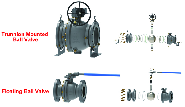
Floating Ball Valve
The ball is not anchored. It rests between two seats and is free to move slightly. Under line pressure, the ball is pushed downstream against the downstream seat, creating a tight seal. This is a self-energizing design: the higher the pressure, the tighter the seal. However, the entire force of the line pressure acts on the ball and seats, which increases operating torque.
Trunnion-Mounted Ball Valve
The ball is fixed on upper and lower trunnion bearings. It does not move under pressure. Instead, spring-loaded seats are pushed against the ball to create the seal. The line pressure does not push the ball against the seat; it actually helps the seats seal. This design separates the sealing force from the line pressure, resulting in lower and more predictable operating torque.
Key implication: Floating valves rely on line pressure for sealing. Trunnion valves rely on mechanical spring force plus line pressure assist. This is why trunnion designs are preferred for larger sizes and higher pressures.
2. Size and Pressure Boundaries: Where Floating Ends
The practical boundary between floating and trunnion designs is determined by torque, seat stress, and actuator feasibility.
| Parameter | Floating Ball Valve | Trunnion Ball Valve |
|---|---|---|
| Typical size range | ½” – 8” | 2” – 60”+ |
| Pressure classes | Class 150 – 600 | Class 150 – 2500 |
| Practical boundary | ~8” at Class 300 | Beyond 8” at Class 300 |
| Class 600 recommendation | Up to 4” | 6” and above |
| Class 900 and above | 1.5” – 2” maximum | Standard for all sizes |
From NSW Valve’s manufacturing records:
The largest floating valve we have supplied for recurring Class 600 service was NPS 6. Beyond that, customers consistently returned to trunnion designs after experiencing actuator sizing and seat maintenance issues. In our experience, the 8-inch Class 300 boundary is not arbitrary—it is where the force required to push the floating ball against the seat begins to exceed the practical limits of soft seat materials and standard actuator packages.
3. Torque Economics: The Hidden Cost Driver
Operating torque is the single most underestimated factor in valve selection. It determines actuator size, air consumption, and ultimately the cost of automation.
The physics of floating valve torque
In a floating ball valve, the torque required to turn the ball is a function of:
T = F_hydraulic × r_ball × μ
Where:
• T = operating torque
• F_hydraulic = force exerted by line pressure on the ball
• r_ball = ball radius
• μ = friction coefficient between ball and seat
Because F_hydraulic increases with pressure and r_ball increases with size, torque rises rapidly. A 4-inch floating valve at 1,000 PSI can require 300–400% more torque than the same valve at atmospheric pressure.
NSW Valve internal benchmark
We tested a 4” Class 600 floating ball valve against a trunnion equivalent at 500 PSI, 1,000 PSI, and 1,480 PSI differential pressure. The floating valve required an average of 2.8× the torque of the trunnion design at 1,000 PSI. This translated to a pneumatic actuator nearly double the size and roughly 60% higher in cost.
The cost flip
A project manager may save 20–30% on the valve itself by choosing floating over trunnion. But if the line requires automation, the actuator upgrade can consume the entire savings—and then some. For manual operation, floating remains cost-effective. For automated service, the breakeven point often falls below the theoretical pressure boundary.
4. Double Block & Bleed and Cavity Pressure Relief
Double Block & Bleed (DBB)
A true DBB function requires that both the upstream and downstream seats seal independently, allowing the cavity between them to be bled. Floating ball valves have only one active sealing seat at a time (the downstream seat). The upstream seat does not provide a reliable independent seal. Therefore, floating ball valves cannot provide true DBB. Trunnion valves with two independent spring-loaded seats can achieve DBB.
Cavity pressure relie
In both designs, trapped pressure in the cavity can expand due to thermal effects. Trunnion valves typically include an automatic cavity relief mechanism. Floating valves rely on the seat design to relieve pressure; this must be verified with the manufacturer for critical applications.
5. The NSW 3-Question Sourcing Framework
To simplify the decision, we use a three-question framework at NSW Valve. If any answer is ambiguous, the trunnion design is the safer specification.
1. Bore size × pressure class
Does the valve fall within the floating boundary?
Rule of thumb: ≤ 8” at Class 300, ≤ 4” at Class 600, ≤ 2” at Class 900+.
2. Actuation requirement
If automated, does torque escalation flip the cost equation?
Check: Compare actuator cost for floating vs trunnion at your actual pressure.
3. Isolation criticality
Does the application require true DBB?
If yes: Trunnion is mandatory.
We have seen too many projects default to floating for cost reasons, only to spend 2–3× the savings on actuator upgrades and maintenance downtime. This framework helps avoid that trap.
Conclusion
Floating ball valves are the most cost-effective choice for small to medium sizes at low to moderate pressures, especially for manual operation. Trunnion-mounted valves become necessary when size, pressure, or isolation requirements exceed the floating boundary.
The key is not to default to one design, but to evaluate torque, actuation, and isolation needs together. Use the NSW 3-Question Framework as a starting point, and consult your valve manufacturer for application-specific data.Need a floating ball valve for your pipeline?
NSW Valve manufactures precision floating ball valves in Class 150–600, with custom materials including WCB, CF8, CF8M, duplex, and high-alloy options.
View Floating Ball Valve Specifications →
About the author
David Chen is a Senior Application Engineer at NSW Valve with 12 years of experience in valve selection for oil & gas, chemical, and power generation projects. He has supported over 200 valve sourcing projects across Asia, Europe, and North America.
Technical review
This guide was reviewed by the NSW Valve Engineering Department. All boundary data and torque profiles reflect NSW Valve’s internal testing and field project records.
Last updated: September 2026
Technical specifications are subject to change without notice. Contact our engineering team for application-specific recommendations.
Post time: Jul-15-2026