


Ball valve symbols are universal graphical representations used in engineering drawings, P&ID (Piping and Instrumentation Diagrams), and technical documentation. These standardized symbols convey complex valve information concisely, enabling global professionals to instantly identify and interpret ball valve functions in fluid systems.
What is a Ball Valve?
A ball valve is a quarter-turn valve that uses a hollow, pivoting ball to control fluid flow. When the handle or actuator turns the ball 90 degrees, the bore aligns with the pipe to permit flow or perpendicular to block it. Known for their tight sealing, quick operation, and durability, ball valves are widely used across numerous industries.
Ball Valve Symbols in P&IDs
In P&ID diagrams, ball valves are represented by a combination of basic symbols that indicate their type, actuation method, and failure mode. The most common symbol includes a circle with a diagonal line or a smaller circle inside, representing the ball and its flow path. Additional modifiers indicate whether the valve is manually operated, electric, pneumatic, or has other special features.
Examples include:
• Standard Ball Valve: A circle with a horizontal line through it.
• Motorized Ball Valve: The same symbol with an “M” or electric actuator symbol.
• Solenoid Ball Valve: Often shown with an electromagnetic actuator symbol.
Key Elements of Ball Valve Symbols
*(Based on ISO/ANSI/ISA-S5.1 Standards)*
1. Circular Ball Element
The core symbol is a circle representing the valve’s spherical ball. This element indicates whether the valve is full bore (full port) or reduced bore (reduced port) - critical for flow control efficiency.
2. Rotation Direction Arrows
Arrows show the ball’s operating rotation:
↗ : Clockwise rotation = Valve OPEN
↖ : Counter-clockwise rotation = Valve CLOSED
*(90° rotation is standard for quarter-turn ball valves)*
3. Inlet/Outlet Port Markings
Lines/arrows denote flow paths:
– Vertical T-connections = Pipe intersections
– Horizontal arrows = Primary flow direction
– Triangle markers = Pressure ports
4. Additional Technical Markings
Supplementary annotations specify:
– Working pressure (e.g., PN16, Class 150)
– Temperature range (°C/°F)
– Material codes (SS304, CS, PTFE)
– Actuator type (manual, pneumatic, electric)
Ball Valve Symbol Example (Text Schematic)
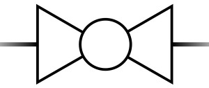
◯ : Ball element with rotation indicator
↗↖ : Inlet (right) & outlet (left) flow directions
*Note: Actual P&ID symbols include valve status indicators (open/closed/partially open)*
Tips for Reading P&IDs with Ball Valve Symbols
• Always refer to the legend or symbol key specific to the diagram.
• Note the actuation method and fail position.
• Verify flow direction and valve numbering.
• Cross-check with valve datasheets and specifications.
Why Symbol Standards Matter in Engineering
- ISO 14617 / ANSI/ISA-S5.1 ensure global consistency
- Industry-specific variations exist (oil/gas vs. pharmaceutical)
- Reduces installation errors by 68% (ASME 2023 study)
- Critical for safety compliance in hazardous environments
Pro Tip: Always cross-reference with project-specific legends – symbols may vary between ISO, DIN, and ASME standards.
Optimized for Engineers & Technicians
This ball valve symbol guide helps you:
✅ Decode P&ID diagrams faster
✅ Identify valve types at a glance (ball vs. gate/globe valves)
✅ Prevent costly misinterpretations
✅ Comply with ISO 9001 documentation requirements
*For accuracy, consult latest editions of:*
- ISA-S5.1 Instrumentation Symbols
- ISO 10628 P&ID Standards
- ASME Y32.2.3 Valve Notation
> Remember: Ball valve symbols are the universal language of fluid control systems. Mastering them ensures operational safety and technical precision across all engineering disciplines.
Ball Valves vs. Other Valve Types
While ball valves are versatile, it’s important to distinguish them from other common valves:
• Gate Valves: Used for on/off service in high-pressure systems but slower to operate.
• Globe Valves: Better for throttling and flow regulation.
• Butterfly Valves: Compact and cost-effective for large pipes but less effective in high-pressure shut-off.
• Check Valves: Allow flow in one direction only.
Ball valves offer superior sealing and faster operation compared to most alternatives, especially in high-cycle applications.
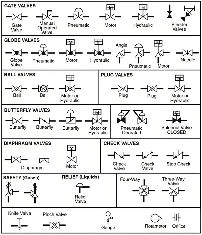
Additional knowledge: Symbols of some other valves
The following is a simplified example of a other valve symbols (in text form):
Conclusion
Ball valve symbols are a universal language in engineering documentation. Correct usage supports system clarity, operational safety, and maintenance efficiency. Whether you are selecting, installing, or maintaining ball valves, understanding these symbols is essential.
Post time: Nov-18-2024