


Introduction: The Critical Role of the Ball Valve Handle in Process Safety
In high-stakes industrial environments—oil and gas transmission pipelines, petrochemical refineries, and heavy processing facilities—the humble ball valve handle or lever operator is a pivotal safety device. It provides the essential human-machine interface for quarter-turn flow control, enabling operators to isolate hazardous media, regulate process variables, and execute emergency shutdowns.
However, these components endure relentless punishment: cyclical mechanical stress, corrosive atmospheric conditions, extreme thermal cycling, and operational fatigue. Over time, a lever can become bent, suffer severe corrosion, or develop mechanical play. A compromised handle not only impedes smooth operation but also poses a critical safety hazard. It can prevent absolute flow isolation during an emergency, lead to gland packing damage from improper torque, or even result in a dangerous stem blowout if maintenance is attempted incorrectly.
Replacing a handle on an industrial-grade valve—such as those built to API 6D standards—is far more complex than loosening a top nut on a garden faucet. It demands strict adherence to line depressurization protocols, precise stem alignment verification, and the use of calibrated torque tools to protect the integrity of the valve’s pressure boundary.
This guide is authored for plant maintenance engineers, reliability technicians, and operations personnel. It provides a comprehensive, safety-first walkthrough for replacing standard lever handles and locking devices. Additionally, it outlines critical decision points for upgrading to enclosed worm gear operators when manual torque becomes unmanageable.
(Looking for factory-direct replacement handles, locking kits, or custom lever operators? Explore our industrial Ball Valve Accessories & Spare Parts or contact our technical support team with your stem dimensions and top flange pattern.)
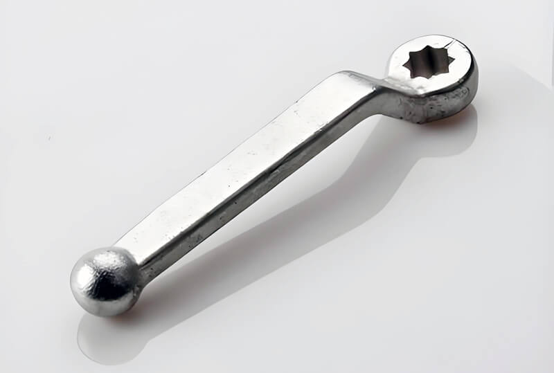
Pre-Maintenance Safety Protocols: Achieving a Zero-Energy State
Before any tool touches a valve stem, you must verify that the system is in a zero-energy state. Skipping these steps can result in catastrophic injury or equipment damage.
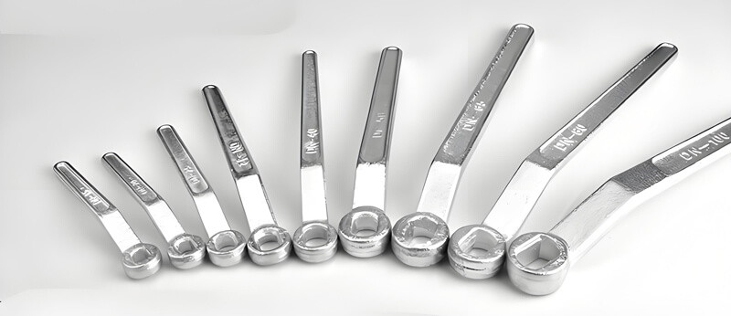
1. Rigorous Lockout/Tagout (LOTO) Implementation
LOTO is not a suggestion; it is an inviolable safety procedure. Isolate all energy sources feeding the valve station. This includes:
- Electrical supply to any actuated valves.
- Pneumatic supply to positioners or actuators.
- Process supply upstream and downstream of the valve.
Apply personal LOTO tags and locks to every isolation point. This prevents inadvertent line pressurization while maintenance is underway.
2. Complete Line Depressurization and Venting
Even with upstream isolation, trapped pressure can remain in the valve body cavity. This is a frequent and deadly oversight.
- Isolate the section: Verify that the upstream and downstream block valves are closed and locked.
- Bleed residual pressure: Use the double block and bleed (DBB) drain valve or the body bleed plug to safely vent any trapped pressure to a safe location or flare. Monitor the pressure gauge to confirm it reads zero.
- Never assume: Always treat the valve as if it is under pressure until you have personally verified it.
3. Thermal Risk Mitigation
Process lines often operate at extreme temperatures.
- For high-temperature services, allow the valve body to cool to a safe handling temperature. Thermal burns are a serious risk.
- For cryogenic services, ensure the valve has warmed to ambient conditions to prevent metal embrittlement and injury from cold contact.
Essential Tools & Technical Verification Checklist
Efficiency and safety depend on having the right tools and information before starting.
| Tool / Item | Purpose | Critical Notes |
|---|---|---|
| Calibrated Torque Wrench | Tighten retaining nut to exact spec | Prevents over-compression of gland packing. Must have calibration certificate. |
| Open-End Wrench Set | Hold lower gland nut during disassembly | Prevents stem rotation when loosening/tightening upper nut. |
| Replacement Handle Assembly | The new lever or handle | Must match top flange and stem drive configuration (e.g., ISO 5211). |
| Lock Washer & Locking Plate | Replacement locking device | Ensure it matches the stem thread size and pitch. |
| Wire Brush & Solvent | Clean exposed stem and flats | Removes corrosion and debris for accurate alignment. |
| Anti-Seize Compound | Optional, for stem threads | Reduces galling and aids future disassembly (check plant policy). |
Stem Connection Verification – A Crucial Step
Before you unbox your new handle, identify your valve stem’s drive configuration. Using the wrong handle is a common mistake.
- Double-D Flat Stem: The most common type for smaller valves. The handle has two flat faces that fit over a corresponding flat on the stem.
- Square Drive Shaft: A square broached end. The handle fits over the square, offering four positions.
- Keyed Stem: Features a key and keyway for a single, correct orientation.
- Splined Stem: Uses a series of fine teeth for high-torque applications.
Inspect the top of your valve stem or refer to the manufacturer’s O&M manual to confirm the type.
Step-by-Step Guide: Replacing the Handle on an API 6D Ball Valve
With safety protocols in place and tools gathered, follow these steps precisely.
1 Step 1: Remove the Stem Retaining Nut & Damaged Lever
- If your valve features a lower gland nut, use an open-end wrench to hold it stationary.
- Using a suitable wrench or socket, turn the upper stem retaining nut counterclockwise to loosen and remove it.
- Carefully lift off the lock washer, the locking plate device, and the damaged lever arm.
- Inspect the threads on the exposed stem. Look for signs of galling, severe corrosion, or stripping. Any damage may require a new stem, which is a more complex repair.
2 Step 2: Inspect the Valve Stem, Gland Flange & Packing Area
With the handle removed, you have a clear view of the stem and packing area. This is an ideal opportunity to perform a preventative check.
- Search for fugitive emissions: Look for any signs of process media weeping around the stem. This indicates packing failure and must be addressed.
- Check for media buildup or corrosion: Clean the exposed stem flats thoroughly using a wire brush and solvent. The drive flats must be clean for the new handle to seat correctly.
- Inspect for stem scoring: Scratches or grooves on the stem can damage new packing and create leak paths.
- Address packing leakage now: If you observe evidence of leakage, do not proceed with the handle replacement. You must adjust or replace the gland packing according to your valve’s O&M manual before installing the new handle. Installing a new handle on a leaking valve masks the problem and is poor practice.
3 Step 3: Align the New Lever Operator with Valve Position (Open/Closed)
This step is where many maintenance errors occur. The new handle must be phased correctly with the internal ball.
- Understand the mechanics: Industrial ball valves have an internal travel stop plate that restricts rotation to a precise 90 degrees. The handle’s stop tab must engage with the valve body’s travel stop pins.
- Confirm internal ball position: The valve’s internal ball port must align with the pipeline flow axis:
- Parallel to pipe = Open position.
- Perpendicular to pipe = Closed position.
- Mount the new handle: Slide the new lever handle over the stem flats. Rotate the handle so its internal stop tab is correctly positioned between the travel stop pins. For a closed valve, the handle should point perpendicular (or as per your plant’s convention) to the pipeline.
4 Step 4: Reinstall Retaining Hardware & Torque to Specification
This final mechanical step is critical for long-term reliability.
- Place the locking plate and lock washer over the stem.
- Hand-start the retaining nut onto the stem to avoid cross-threading.
- Torque application: Use your calibrated torque wrench to tighten the nut to the manufacturer’s specified torque value. This value is found in the valve’s O&M manual. Do not guess or use a “standard” torque. Over-tightening can compress the gland packing unevenly, drastically increasing operating torque and causing premature packing wear. Under-tightening can allow the handle to loosen over time.
- Cycle the valve: After torquing, manually cycle the valve fully open and fully closed at least two times. This confirms:
- Smooth, uninterrupted 90° operation.
- The stop tab is engaging the stops correctly.
- The handle indicates the correct position at both extremes.
Common Installation Mistakes and Their Consequences
Avoid these frequent errors to ensure a safe and durable repair.
| Mistake | Consequence |
|---|---|
| Attempting disassembly under line pressure | Catastrophic stem blowout. The stem can become a dangerous projectile, and high-pressure media can cause severe injury or death. This is the most critical risk. |
| Misaligning travel stops (90° out of phase) | The handle indicates “Open” when the ball is actually “Closed,” and vice-versa. This can lead to severe operational errors, process upsets, and damage to downstream equipment. |
| Over-tightening the stem retaining nut | Compresses the gland packing unevenly. Dramatically increases operating torque, accelerates packing wear, and can lead to stem seizure. |
| Using an extension pipe on a lever | This is an unsafe workaround for high torque. It multiplies force and can easily bend the valve stem, damage the ball, or compromise the packing, leading to leaks. |
| Installing a mismatched handle | The handle will fit poorly, may slip under load, and will not provide reliable control. |
Upgrade Options: When to Transition from a Lever to a Worm Gear Operator
Standard lever handles are economical and efficient for small-bore valves (typically ≤ 4 inches, Class 150/300). However, as valve size or differential pressure increases, the required operating torque increases significantly.
Recognize these signs that it’s time for an upgrade:
- Operators struggle to turn the handle manually.
- You are considering using a “cheater bar” or pipe extension (an unsafe practice).
- The operating torque is so high that the lever arm itself flexes or shows signs of fatigue.
- Valve operation is slow and imprecise.
In these scenarios, upgrading to an Enclosed Worm Gear Operator is the correct engineering solution. Benefits include:
- Mechanical Advantage: A gearbox multiplies the operator’s input force, making high-torque operation effortless and safe.
- Precise Control: The gearing allows for finer, more controlled movement.
- Self-Locking: Most worm gears are self-locking, meaning they will not back-drive under flow/pressure, preventing water hammer.
- Safety: Eliminates the need for unsafe lever extensions and reduces the risk of operator injury.
When replacing a handle, it’s the perfect time to evaluate if a gear operator upgrade is a more prudent long-term investment for your facility.
Conclusion and Actionable Takeaways
Replacing a handle on an industrial API 6D ball valve is a task demanding respect for process safety and attention to technical detail. By adhering to strict LOTO and depressurization protocols, correctly identifying your stem type, precisely aligning the new lever, and torquing to specification, you ensure the continued reliable and safe operation of your process system.
Regularly inspect handles for wear, and never hesitate to upgrade to a gear operator when the application demands it.
Need a replacement handle, a complete locking kit, or help selecting a gear operator? NSW Valve offers a comprehensive range of API-6D-compliant ball valve accessories. Contact our technical experts today with your valve details, and we’ll help you find the right part for a safe and efficient repair.
Link to related articles: How to Fix a Leaking Ball Valve
Post time: Apr-14-2025