


Product Tagline: *Accurate Dimensioning, Port Selection, and Flange Standards for Seamless Industrial Piping Installation.*
—
1. Introduction: Why Ball Valve Dimensions Matter
Accurate valve dimensions are not a detail to be deferred to the procurement stage—they are a design constraint that governs flow dynamics, piping layout, and installation sequencing. In industrial process plants, refineries, and commercial piping systems, a ball valve that meets the pressure rating but misses the face-to-face dimension by even a few millimeters can trigger a cascade of consequences: flange misalignment, pipe stress at welded joints, pressure drop anomalies that compromise system efficiency, and costly on-site rework.
The dimensional framework for ball valves is standardized precisely to prevent these failures. ASME B16.10 and its European counterpart EN 558 establish the laying lengths that make valves of the same type, size, and pressure class interchangeable between manufacturers . When a piping engineer specifies a valve by standard designation rather than by a single manufacturer’s part number, the dimensional data in this guide becomes the bridge between design intent and installed reality.
For technical engineers, these dimensions determine whether an actuator will fit within the clearance envelope. For procurement professionals, they determine whether the valve received at the site will drop into the pipe spool without modification. This guide addresses both audiences with the dimensional rigor each requires.
—
2. Understanding Ball Valves Dimensions & Standards
Key Measuring Parameters
Every ball valve is defined by four critical dimensions:
- Face-to-Face (L): The distance between the inlet and outlet flange faces for flanged valves, or the end-to-end length for butt-weld and socket-weld connections. Governed by ASME B16.10 for flanged and weld-end valves .
- Flange Outer Diameter (D): The outside diameter of the end connection flange, specified by ASME B16.5 for flanged ends, or the thread/weld specification for NPT, BSPT, or Socket Weld connections.
- Bore Diameter (d): The inner diameter of the ball passage. Distinguishes Full Port (full bore) from Reduced Port (standard bore) designs—a distinction with direct flow and cost implications addressed in Section 6.
- Center-to-Top Height (H) & Handle Clearance: The vertical distance from the valve centerline to the top of the stem or actuator mounting pad. Critical for determining actuator envelope and manual operation clearance.
Short Pattern vs. Long Pattern: A Critical Distinction
ASME B16.10 defines two face-to-face patterns for flanged ball valves. The short pattern is the compact lay length used for most ball valves, while the long pattern provides an extended lay length . For ball valve sizes 6” and larger, the standard offers both alternatives; for smaller sizes, the distinction is often less pronounced or the patterns are identical .
This is not an academic distinction. A procurement specification that states only “3” Class 150 ball valve” without specifying short or long pattern leaves the door open for supplier substitution. If the pipe spool was designed for a long-pattern valve and a short-pattern unit arrives, the gap cannot be closed without spacers or pipe modification. The reverse scenario—short-pattern design, long-pattern delivery—may not fit the available space at all.
For sizes 6” and above, specify the pattern explicitly on the purchase order. For smaller sizes, verify against the manufacturer’s datasheet, as patterns converge in this range but supplier interpretation may vary.
Structural Diagram
A standard flanged ball valve body is annotated with the four dimensions above: L (face-to-face), D (flange OD), d (bore diameter), and H (center-to-top height). These four values, read together, define whether a valve will fit the pipe spool, mate with adjacent flanges, and accommodate the chosen actuation method.
—
3. Dimensional Breakdown: Small-Bore Ball Valves (1/2” to 2”)
Small-bore ball valves dominate instrument, utility, and process lines where precise flow control and compact installation envelopes are priorities. The dimensional progression from 1/2” through 2” reflects both the increasing flow area and the increasing structural demands on the valve body.
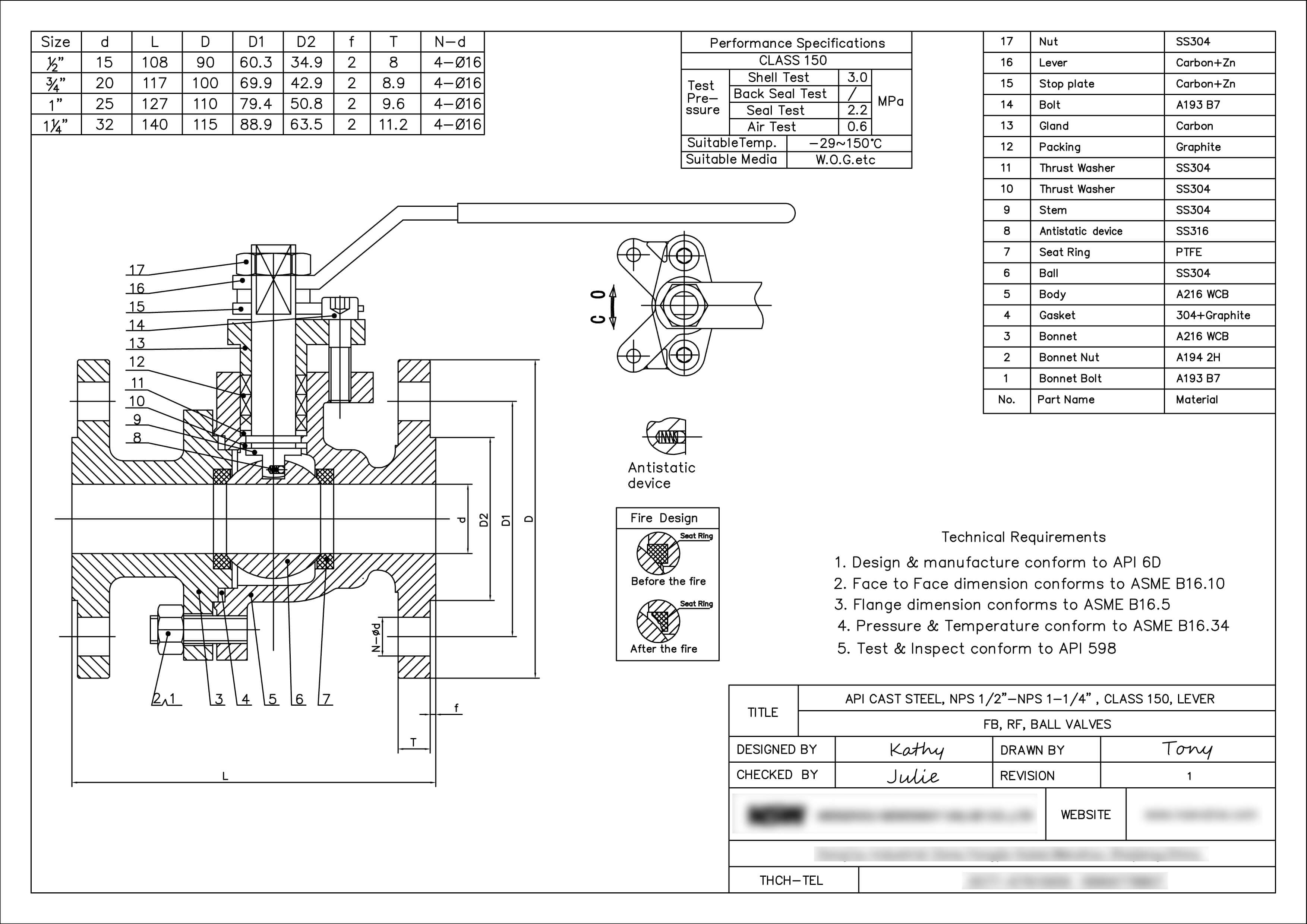
1/2 Ball Valve Dimensions
- Typical Applications: Instrument isolation, chemical feed lines, sampling points.
- Nominal Bore: 15 mm (0.50”)
- Key Specs: For threaded (NPT) ends, the end-to-end length is significantly shorter than flanged equivalents. For Class 150 flanged, the face-to-face dimension follows ASME B16.10 short pattern at approximately 108 mm . Confirm whether the application requires a short-pattern or long-pattern valve before finalizing the pipe spool.
3/4 Ball Valve Dimensions
- Typical Applications: Auxiliary utility lines, compressed air, low-pressure condensate.
- Nominal Bore: 20 mm (0.75”)
- Key Specs: The dimensional comparison between 2-piece and 3-piece bodies is most relevant here. A 3-piece body permits in-line maintenance without removing the valve from the pipe, but the added joint thickness may marginally affect the overall face-to-face dimension. For Class 150 flanged, face-to-face is approximately 117 mm .
1 Ball Valve Dimensions
- Typical Applications: Plant branch lines, fuel gas piping, industrial water treatment lines.
- Nominal Bore: 25 mm (1.00”)
- Key Specs: The ISO 5211 direct mounting pad becomes a relevant dimensional consideration at this size. The pad’s bolt circle diameter and square stem drive determine which actuators can be mounted without an adapter bracket—a procurement detail that saves both cost and vertical clearance.
1-1/2 Ball Valve Dimensions
- Typical Applications: Chemical batching lines, pump discharge manifolds, steam utility streams.
- Nominal Bore: 40 mm (1.50”)
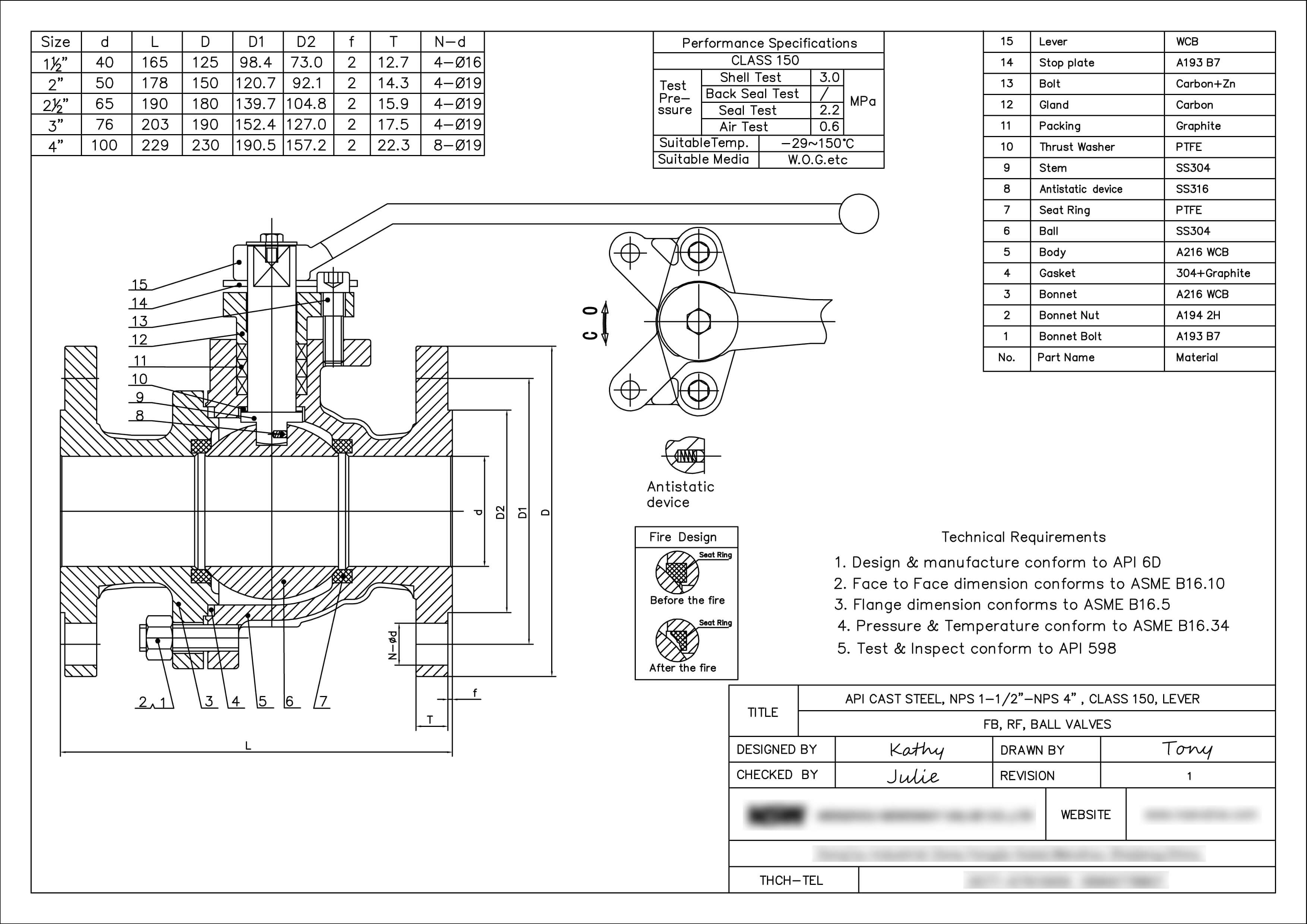
- Key Specs: This size marks a transition point where connection type materially affects dimensions. Threaded NPT and socket-weld bodies are substantially shorter end-to-end than flanged bodies, which must follow ASME B16.10 face-to-face lengths. The flange OD for Class 150 is 127 mm . Procurement specifications must state the connection type explicitly—substituting a threaded body for a flanged design will not match the pipe spool.
2 Ball Valve Dimensions
- Typical Applications: Primary process lines, oil & gas manifolds, municipal water intake systems.
- Nominal Bore: 50 mm (2.00”)
- Key Specs: Face-to-face dimensions diverge significantly across pressure classes at this size. Class 150 short pattern is approximately 178 mm, while Class 300 increases to approximately 216 mm . Weight increases correspondingly. For procurement, the pressure class must be confirmed before the face-to-face dimension can be treated as a fixed constraint.
—
4. Dimensional Breakdown: Medium & Large-Bore Ball Valves (3” and Above)
At 3” and above, ball valve dimensions are dominated by the physics of the ball itself. The ball diameter required for full-port flow grows non-linearly with valve size, driving body dimensions and, in many cases, requiring gear operators or actuated control.
3 Ball Valve Dimensions
- Typical Applications: Main utility supply headers, hydrocarbon process loops, cooling water distribution.
- Nominal Bore: 80 mm (3.00”)
- Key Specs: The 3” size represents the practical transition point to gear operators for manual valves—lever operation becomes unwieldy at the torque required. Face-to-face dimensions across ASME pressure classes: approximately 203 mm for Class 150, 241 mm for Class 300 . Flange OD for Class 150 is 190 mm .
4 Ball Valve Dimensions
- Typical Applications: Transmission pipelines, refinery headers, heavy cooling water loops.
- Nominal Bore: 100 mm (4.00”)
- Key Specs: The dimensional profile diverges significantly between Trunnion-mounted and Floating ball designs at this size. Trunnion-mounted valves handle higher pressures and larger sizes by anchoring the ball, but the body dimensions—and therefore the face-to-face and center-to-top height—differ from floating designs. Actuator mounting clearance must be calculated against the specific design, not assumed from nominal size alone.
—
5. Ball Valve Dimensions Reference Table (ASME Class 150 Flanged)
Important: The table below presents short-pattern dimensions, which are standard for most ball valve applications. For sizes 6” and above, verify whether short or long pattern is required for your pipe spool. For 3” and 4”, confirm the pattern against the manufacturer datasheet, as both may be offered .
| Nominal Valve Size | Full Port Bore (d) | Face-to-Face (L) Short Pattern, ASME B16.10 | Flange OD (D) ASME B16.5 | Center to Top Height (H) |
| 1/2 Ball Valve (1/2”) | 0.50” (15 mm) | 4.25” (108 mm) | 3.50” (89 mm) | 2.6” (66 mm) |
| 3/4 Ball Valve (3/4”) | 0.75” (20 mm) | 4.60” (117 mm) | 3.88” (98 mm) | 2.9” (74 mm) |
| 1 Ball Valve (1”) | 1.00” (25 mm) | 5.00” (127 mm) | 4.25” (108 mm) | 3.4” (86 mm) |
| 1-1/2 Ball Valve (1-1/2”) | 1.50” (40 mm) | 6.50” (165 mm) | 5.00” (127 mm) | 4.4” (112 mm) |
| 2 Ball Valve (2”) | 2.00” (50 mm) | 7.00” (178 mm) | 6.00” (152 mm) | 5.1” (130 mm) |
| 3 Ball Valve (3”) | 3.00” (80 mm) | 8.00” (203 mm) | 7.50” (190 mm) | 7.8” (198 mm) |
| 4 Ball Valve (4”) | 4.00” (100 mm) | 9.00” (229 mm) | 9.00” (229 mm) | 9.8” (248 mm) |
Notes on the table:
- Face-to-face values are short pattern per ASME B16.10. For long pattern at 6” and above, dimensions differ—consult the standard directly.
- Flange OD values are Class 150 per ASME B16.5 .
- Center-to-top height (H) is approximate and varies by manufacturer and handle/operator configuration. Use manufacturer datasheets for final clearance calculations.
—
6. Full Port vs. Reduced Port: How Inner Dimensions Affect Flow
The bore diameter (d) is the single dimension with the most direct impact on system hydraulics.
Full Port (Full Bore): The ball passage diameter equals the pipe inner diameter. This provides the maximum flow coefficient (Cv), minimal turbulence, and zero flow restriction. Full port is the specification of choice for applications where pressure drop is critical or where pigging is required.
Reduced Port (Standard Bore): The ball passage is typically one nominal size smaller than the pipe ID. The trade-off is deliberate: a smaller ball requires a smaller body, which reduces weight and cost. The penalty is a measurable pressure drop across the valve. For 6” Class 150 ball valves, reduced port means a 4” bore passage, yielding roughly 44% less flow area than a full-port equivalent .
The procurement decision is not simply “full port is better.” In utility lines where pressure drop is not constraint, a reduced port valve may represent significant cost savings with acceptable performance. In process lines where pump head calculations assume full-port Cv, substituting reduced port can cascade into system-wide performance shortfalls.
—
7. Procurement & Selection Checklist for Piping Engineers
- Verify Pipe Schedule (Sch 40, Sch 80, etc.) against the valve bore diameter (d). Full port must match pipe ID; reduced port must be accounted for in flow calculations.
- Confirm ASME Pressure Rating (Class 150, 300, 600) before treating face-to-face as a fixed value. Higher classes increase laying length and flange OD .
- Specify Short Pattern or Long Pattern for sizes 6” and above. Do not leave the choice to the supplier .
- Calculate Clearance Envelope for stem travel, lever operation, gear operator, or actuator installation. Center-to-top height (H) from the manufacturer datasheet, not this guide.
- Confirm Connection Ends (NPT, BSPT, Flanged RF/RTJ, Butt-Weld, Socket-Weld). Dimensional profiles differ materially between connection types at the same nominal size.
- For 1-1/2 Ball Valve specifically: Confirm threaded vs. flanged ends against the pipe spool drawing. Substitution between connection types is not dimensionally interchangeable.
—
8. Frequently Asked Questions (FAQ)
Q1: Are face-to-face dimensions interchangeable between a 3 Ball Valve and a 4 Ball Valve?
No. ASME B16.10 specifies distinct laying lengths for each size and pressure class: approximately 203 mm for 3” Class 150 and 229 mm for 4” Class 150 . The difference accounts for the larger ball diameter and seating geometry required for full-port flow at the larger size. A 3” valve cannot substitute for a 4” valve in a fixed pipe spool without modification.
Q2: What is the main dimensional difference between a 1-1/2 Ball Valve in NPT vs. Flanged ends?
Threaded NPT bodies are significantly shorter end-to-end than flanged bodies of the same nominal size. Flanged 1-1/2” Class 150 valves follow ASME B16.10 face-to-face lengths (approximately 165 mm short pattern) to accommodate standard pipe flanges and bolting . Threaded bodies have no flange, so their end-to-end length is governed by thread engagement requirements, not flange mating dimensions. **These two configurations are not interchangeable in a pre-fabricated pipe spool.**
Q3: Which dimension determines the top actuator mounting interface?
The ISO 5211 pad dimensions, which define the bolt circle diameter, square stem drive size, and the center-to-top height (H). The ISO 5211 standard ensures that actuators from different manufacturers can mount to the valve without adapter plates. When procuring an automated ball valve, specify the ISO 5211 size alongside the valve size and pressure class.
Q4: For a 6” Class 150 ball valve, can I get a full-port design in a short-pattern body?
No. The 6” short-pattern ball valve cannot be offered in full port. The full-port ball diameter (approximately 247 mm) exceeds the available internal clearance in the 267 mm short-pattern body after accounting for seats, seals, and flange geometry. Full-port 6” Class 150 ball valves require the long-pattern body. If your pipe spool is designed for short pattern, you must accept reduced port or modify the spool .
—
9. Summary: Dimensions as the Interface Between Design and Delivery
Ball valve dimensions are not a single number to be looked up—they are a set of interdependent values that must align across the valve, the pipe spool, the flange specification, and the actuation method. For piping engineers, the critical variables are face-to-face pattern (short vs. long), bore type (full vs. reduced), and ISO 5211 pad size. For procurement professionals, these same variables determine whether the valve received at the site will install without modification.
The reference table in Section 5 provides the dimensional framework for Class 150 flanged ball valves from 1/2” through 4”. For sizes 6” and above, and for pressure classes above 150, consult ASME B16.10 directly and confirm pattern requirements against the pipe spool design before issuing the purchase order.
Post time: Sep-26-2026