


Introduction: Why Actuation Selection Matters
In the demanding environments of oil and gas refineries, petrochemical plants, power generation facilities, and municipal water infrastructure, the reliable operation of ball valves is non-negotiable. These critical components control the flow of everything from high-pressure hydrocarbons to corrosive chemicals and potable water. Yet, even the highest-quality ball valve is only as effective as the mechanism used to turn it.
Ball valves operate on a simple quarter-turn (90°) principle: a rotating sphere with a cylindrical bore either aligns with the pipeline to permit flow or turns perpendicular to block it. However, the ball valve operation method selected—whether manual, geared, or powered—determines not only how easily the valve turns but also its safety profile, maintenance frequency, and suitability for automation.
This comprehensive guide examines the full spectrum of ball valve actuation options, from the familiar manual ball valve handle to heavy-duty ball valve gear box operators, and from high-speed ball valve pneumatic actuator systems to precision ball valve electric actuator units. By the end, engineering teams, procurement specialists, and plant maintenance personnel will have a clear framework for specifying the correct actuation package for their specific application.
Need expert assistance selecting the right actuator? Contact our engineering team with your valve specifications for a free recommendation.
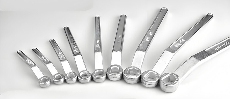
Manual Ball Valve Operation: Handles and Gearboxes
For many applications, manual ball valve operation remains the most practical and economical choice. These solutions require no external power source, are inherently simple to maintain, and provide reliable performance for isolation duties in utility lines, bypass loops, and smaller process branches.
Ball Valve Handle (Lever Operator) – Simple, Direct, and Cost-Effective
The ball valve handle—also referred to as a lever operator—is the most widely recognized manual interface for ball valves. Its simplicity is its greatest strength, but engineers must understand its limitations to avoid unsafe operating conditions.
Mechanical Design and Kinematics
A typical ball valve handle consists of a formed metallic lever (stainless steel, carbon steel with protective coating, or ductile iron) that connects directly to the valve stem. The handle’s broached bore matches the stem’s drive configuration, which typically falls into one of three categories:
| Stem Type | Description | Common Applications |
|---|---|---|
| Double-D Flat | Two parallel flats ground onto the stem end | Most common for ½”–4″ industrial valves |
| Square Drive | Four-sided broached stem end | Older designs and some high-torque manual valves |
| Keyed / Splined | Single keyway or fine spline teeth | High-security applications requiring single orientation |
Rotating the lever through its 90° arc directly turns the stem and the attached ball. In the open position, the handle aligns parallel to the pipeline; in the closed position, it stands perpendicular—providing immediate visual confirmation of valve status.
Application Boundaries and Torque Limitations
While the lever handle is economical and effective, it is not suitable for all conditions. Engineering guidelines generally restrict manual lever operation to:
- Valve sizes: ≤ 4 inches (DN100)
- Pressure classes: Up to Class 300 (PN 40)
- Breakaway torque: Typically < 200 Nm (150 lbf·ft)
- Differential pressure: Low-to-moderate ΔP across the valve
Attempting to operate larger valves or high-pressure services with a standard handle presents serious risks. When the required breakaway torque exceeds approximately 200 Nm, manual lever operation becomes physically strenuous. Operators may resort to using extension pipes—commonly called “cheater bars”—which multiply leverage but dangerously overstress the valve stem. This practice frequently leads to stem bending, gland packing damage, or catastrophic stem blowout.
Critical Safety Note: The use of pipe extensions on manual lever handles is strictly prohibited by API RP 574 and most plant safety protocols.
Locking Devices for LOTO Compliance
Modern industrial ball valve handles incorporate safety features beyond simple leverage. Most lever handles are equipped with integrated locking plates—slotted metal plates that accept standard padlocks. This enables full Lockout/Tagout (LOTO) compliance, allowing maintenance personnel to positively lock the valve in the closed position during line work. Some designs also feature spring-loaded detent pins that engage with a stop plate, providing tactile confirmation and positive position retention at both 0° and 90°.
Ball Valve Gear Box – Mechanical Advantage for Large-Bore Valves
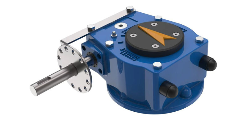
When valve sizes reach 6 inches or larger, or when system pressures climb to Class 600 and beyond, manual ball valve operation through a simple lever becomes impractical—even dangerous. The solution is the ball valve gear box, a mechanical torque multiplier that dramatically reduces the physical effort required to turn the valve.
Working Principle: Worm Gear Mechanics
A ball valve gear box employs a self-locking worm gear mechanism. Turning the handwheel rotates a hardened steel worm screw, which drives a worm gear (or gear segment) attached to the valve stem. The gear ratio—typically ranging from 30:1 to over 120:1—multiplies the operator’s input force while simultaneously reducing the rotation speed. The result: a full 90° valve stroke requires multiple turns of the handwheel, but the rim pull force on the handwheel remains well within safe ergonomic limits.
Key mechanical advantages:
- Torque multiplication: Ratios as high as 120:1 allow a single operator to handle valves requiring up to 10,000 Nm of output torque.
- Self-locking: The worm gear design inherently prevents back-driving. The valve will not rotate under flow pressure without deliberate handwheel input.
- Controlled speed: The multi-turn operation prevents rapid, slam-shut closure that could induce water hammer.
Gearbox Housing and Sealing
Industrial-grade gearboxes are enclosed in rugged housings, typically rated to IP65 or IP67 for dust and water ingress protection. Units intended for offshore or corrosive environments are available with special epoxy coatings (e.g., 500 μm minimum) and stainless steel fasteners. For cryogenic or high-temperature services, special stem extension designs isolate the gearbox from extreme process temperatures, preserving lubricant integrity and ensuring smooth operation.
Selection Criteria for Gear Operators
| Parameter | Consideration |
|---|---|
| Required output torque | Calculate based on valve size, seat type (soft vs. metal-seated), and maximum ΔP. Apply 30% safety margin. |
| Gear ratio | Higher ratio = lower handwheel force but more turns. Balance operator comfort against operating speed. |
| Mounting interface | Verify ISO 5211 flange pattern and stem connection type. |
| Environmental rating | Select appropriate enclosure (IP65, IP67, IP68) and coating for site conditions. |
| Fail-safe position | Gearboxes alone do not provide fail-safe action; consider actuator addition if required. |
When to choose a gearbox: For valves ≥6″ in critical service, or whenever the calculated operating torque exceeds 200 Nm. A gearbox is the engineered solution; lever extensions are not.
Automated Ball Valve Actuation: Pneumatic and Electric Solutions
In process automation environments, manual ball valve operation is supplemented—or entirely replaced—by powered actuators. These systems enable remote control, integration with distributed control systems (DCS), and critical safety functions such as emergency shutdown (ESD). The two dominant technologies are pneumatic and electric.
Ball Valve Pneumatic Actuator – Speed and Fail-Safe Reliability
The ball valve pneumatic actuator is the workhorse of the oil and gas industry. Its combination of rapid operation, high torque density, and inherent fail-safe capability makes it the preferred choice for critical safety loops and high-cycle process applications.
Operating Principle
A pneumatic actuator converts compressed air energy into mechanical rotary motion. Two primary mechanisms are common:
| Mechanism | Design | Best Suited For |
|---|---|---|
| Rack-and-Pinion | Two opposing pistons drive a central pinion gear via rack teeth. Compact, linear torque curve. | Small-to-medium valves, high cycle life, on-off service. |
| Scotch-Yoke | A piston drives a slotted yoke that converts linear motion to rotation. Non-linear torque output matches ball valve breakaway torque profile. | Large valves, high torque requirements, ESD applications. |
In double-acting designs, air pressure supplied to either side of the pistons drives the valve open or closed. The position is held solely by air pressure; loss of supply pressure leaves the valve in its last position.
Fail-Safe with Spring-Return
The greatest advantage of pneumatic actuation lies in the single-acting (spring-return) configuration. In these units, heavy-duty mechanical springs are compressed during normal operation. Upon loss of instrument air or electrical signal, the springs instantly expand, returning the valve to a pre-defined safe position—Fail-Open or Fail-Closed—within seconds.
Spring-return performance typicals:
- Stroke time: 0.5 to 2 seconds for quarter-turn operation
- Torque range: Up to 100,000+ Nm for large-bore valves
- Fail-safe cycles: Designed for thousands of cycles without spring fatigue
Control Accessories for Pneumatic Actuators
A complete pneumatic actuator package includes several control components:
- Solenoid valves: Electrically pilot the air supply to the actuator.
- Limit switches: Provide position feedback (open/closed) to the DCS.
- Positioners: Enable precise modulating control (4–20 mA input) and throttle the ball for flow regulation.
- Filter-regulator-lubricator (FRL): Conditions the air supply to ensure reliable actuator operation.
- Quick-exhaust valves: Accelerate stroking speed for ESD functions.
Hazardous Area Compatibility
Pneumatic systems are inherently well-suited for hazardous environments. With no electrical components at the valve itself (solenoids can be remotely mounted or certified intrinsically safe), pneumatic actuators are naturally compatible with:
- ATEX / IECEx Zone 1 and 2 (gas/vapor)
- NEC Class I, Divisions 1 and 2
- Offshore platforms and other explosion-risk installations
Ball Valve Electric Actuator – Precision Without Air Infrastructure
When instrument air is unavailable, expensive to install, or when precise modulating control is required, the ball valve electric actuator offers a compelling alternative. These units employ an integrated ball valve motor coupled with a gear reduction train to produce controlled rotary motion.
Core Components of a Motorized Actuator
A complete electric actuator package comprises several key subsystems:
- Ball valve motor: Typically a brushless DC motor or AC induction motor, sized to the required duty cycle.
- Gear reduction train: Planetary, spur, or worm gears that reduce motor speed (typically 2,000–3,600 RPM) to the required 0.5–2 RPM output speed.
- Control electronics: Onboard microprocessor for position control, signal processing, and diagnostics.
- Position feedback: Potentiometer, resolver, or absolute encoder to precisely report valve position to the DCS.
- Limit switches: End-of-travel cutoffs to protect the motor and valve from over-travel.
Precision Modulating Control
One of the defining advantages of electric actuation is its capability for precise modulating control. With a 4–20 mA analog input signal or digital communication (Modbus, Profibus, Foundation Fieldbus), the actuator can position the ball at any degree of rotation—not just fully open or fully closed. This enables:
- Flow metering and dosing control
- Pressure regulation
- Temperature control loops
- Automated batching processes
Accuracy to within ±1% of span is achievable with modern digital actuators, making them suitable for applications that demand tight process control.
Power and Self-Locking
Electric actuators are inherently self-locking. The gear train (particularly worm gear configurations) holds the valve position without consuming power once the target position is achieved. This is energy-efficient and reduces heat generation during stationary periods.
Compact Infrastructure Requirements
The absence of air piping is a significant advantage for electric actuators. Installation requires only:
- Electrical power supply (standard AC or DC voltages)
- Control signal wiring (analog or digital)
- A suitable electrical enclosure (weatherproof or explosion-proof as required)
This makes electric actuation an ideal choice for remote monitoring and control (SCADA) installations, small treatment plants, and retrofitting manual valves with powered operation.
Hazardous Area Options
Unlike pneumatic actuators, electric units have electrical components that must be specially rated for explosive atmospheres. Options include:
- Explosion-proof housings: Certified to ATEX / IECEx for Zones 1, 2, 21, and 22
- Intrinsically safe circuits: Low-energy designs for Zone 0 and Zone 20
- Purged/pressurized enclosures: For large actuators in hazardous areas
When selecting an electric actuator for hazardous duty, always verify the certification matches the site classification.
Technical Comparison Matrix – At a Glance
| Actuation Type | Power Source | Typical Torque Range | Primary Advantage | Best Application | Relative Cost |
|---|---|---|---|---|---|
| Ball Valve Handle | Manual | < 200 Nm | Lowest cost, no power needed | Small-bore isolation, utility lines (≤4″) | $ |
| Ball Valve Gear Box | Manual handwheel | Up to 10,000 Nm | High mechanical advantage, self-locking | Large-bore pipeline isolation (≥6″) | $$ |
| Ball Valve Pneumatic Actuator | Compressed air | Up to 100,000+ Nm | Rapid stroke, spring-return fail-safe | ESD, process automation, hazardous areas | $$$ |
| Ball Valve Electric Actuator | AC/DC power | Up to 30,000 Nm | Precise modulating control, no air required | SCADA, remote sites, dosing applications | $$$ |
Actuation Selection Criteria – A 5-Step Engineering Framework
Selecting the correct actuation method requires systematic evaluation of process conditions, operational requirements, and site infrastructure. Use this five-step framework to guide your decision.
Step 1: Determine Required Operating Torque
Calculate the maximum torque required to operate the valve under worst-case conditions. This includes:
- Breakaway torque (starting friction)
- Running torque (dynamic friction during rotation)
- Seating torque (end-of-stroke compression)
All three values are influenced by:
- Valve size and pressure class
- Seat material (soft PTFE/RPTFE vs. metal-seated)
- Differential pressure (ΔP) across the valve
- Media temperature and lubricity
Rule of thumb: Always apply a 30% safety margin above the calculated breakaway torque. For example, if calculated breakaway is 150 Nm, specify an actuator capable of at least 200 Nm.
Step 2: Define Duty Cycle and Operating Speed
Determine the frequency and speed of valve operation:
| Duty Type | Characteristics | Actuation Recommendation |
|---|---|---|
| Isolation (on-off) | Infrequent operation, full stroke | Gearbox, standard pneumatic, or electric |
| Emergency shutdown (ESD) | Very infrequent, but must act instantly | Spring-return pneumatic (fastest stroking) |
| Modulating control | Continuous positioning, frequent partial strokes | Electric actuator with positioner |
| High cycle | Hundreds of operations per day | Electric or heavy-duty rack-and-pinion pneumatic |
Step 3: Assess Fail-Safe Requirements
System safety philosophy dictates the required behavior upon loss of power, air, or control signal:
- Fail-Closed – Valve closes automatically on loss of power/air. Achieved with spring-return pneumatic actuators or battery-backed electric actuators.
- Fail-Open – Valve opens automatically. Spring-return pneumatic with reverse configuration or special electric actuator with capacitor backup.
- Fail-in-Last-Position – Valve stays where it is. Achieved with double-acting pneumatic (without spring) or self-locking electric actuators.
Step 4: Evaluate Site Infrastructure and Hazard Class
| Site Condition | Pneumatic | Electric |
|---|---|---|
| Instrument air available | Preferred | Alternative |
| No air infrastructure | Challenging (requires compressor) | Preferred |
| Hazardous area (Zone 1) | Inherently suitable | Requires explosion-proof enclosure |
| Remote / unmanned location | Requires dry air system | Preferred (SCADA-compatible) |
| Extreme ambient temperature | Good (air remains functional) | Requires special motors and lubricants |
Step 5: Verify ISO 5211 Mounting Compatibility
Regardless of actuation type, ensure the valve top flange complies with ISO 5211 standards. This standard defines:
- Flange dimensions (bolt circles, pilot diameters)
- Drive stem dimensions (square sizes, engagement depths)
- Torque ratings for each flange size (F05, F07, F10, etc.)
ISO 5211 direct-mounting eliminates the need for separate brackets and couplings, simplifying installation and ensuring proper alignment.
Installation and Maintenance Best Practices
Proper installation and routine maintenance are essential to reliable long-term ball valve operation. Regardless of actuation type, follow these best practices.
Installation Checklist
- Verify valve and actuator are properly aligned.
- Ensure actuator mounting bracket is correctly attached (if not direct-mount).
- Confirm stem connection is fully engaged before tightening.
- Cycle the valve manually (if equipped) to confirm full 90° travel before applying power or air.
- For electric actuators, verify power supply voltage matches motor nameplate.
- For pneumatic actuators, supply clean, dry, lubricated air per ISO 8573-1 standard.
- Perform final torque check on all fasteners.
- Test full stroke with medium pressure applied to confirm leak-free seating.
Maintenance Schedule Guidelines
| Component | Inspection Interval | Typical Maintenance Action |
|---|---|---|
| Lever handle | Quarterly | Check for bending, corrosion, and secure fastening. |
| Gearbox | Annually | Inspect lubricant level; check seal integrity. |
| Pneumatic actuator | Semi-annually | Check air filters and moisture traps; test spring-return stroke speed. |
| Electric actuator | Annually | Verify limit switch settings; check terminal tightness; test backup power (if equipped). |
| All types | Before each plant shutdown | Full functional test from control room and locally. |
Conclusion – Choosing the Right Actuation for Your Ball Valve
Selecting the correct actuation method for a ball valve is a decision with long-term consequences for plant safety, operational efficiency, and maintenance costs.
| Actuation Type | Best Fit Summary |
|---|---|
| Ball Valve Handle | Small-bore, low-torque, infrequent operation—simple and reliable. |
| Ball Valve Gear Box | Large-bore, high-torque manual operation—safe and ergonomic. |
| Ball Valve Pneumatic Actuator | High-speed, fail-safe critical duty—ideal for ESD and hazardous areas. |
| Ball Valve Electric Actuator | Precision control, remote sites, no air supply—versatile and energy-efficient. |
Start by calculating your torque requirements, define your fail-safe philosophy, and evaluate your site infrastructure. With those factors in hand, the appropriate solution becomes clear.
Still uncertain? Our technical team specializes in ball valve actuation selection. Send us your valve specifications—size, pressure class, service conditions, and any special requirements—and we will provide a comprehensive recommendation with torque calculations and datasheets.
Post time: Sep-06-2026