


The Essential Guide to SDV Valves: Safeguarding Critical Industrial Processes
In the high-stakes world of oil & gas, petrochemicals, power generation, and other process industries, safety isn’t just a priority; it’s an absolute imperative. At the heart of protecting personnel, assets, and the environment from catastrophic events like fires, explosions, or toxic releases lies a crucial piece of equipment: the Shutdown Valve (SDV), often also referred to as an Emergency Shutdown Valve (ESDV). But what exactly is an SDV valve, and why is it so vital?
An SDV Valve (Shutdown Valve) is a specially designed and certified automatic valve integrated into a Safety Instrumented System (SIS). Its sole, critical purpose is to rapidly and reliably isolate a section of piping or equipment upon receiving a signal from the SIS, triggered by the detection of a hazardous condition (e.g., high pressure, high temperature, gas leak, fire, equipment failure). This swift isolation prevents the escalation of the incident by stopping the flow of hazardous fluids (liquids, gases, or multiphase).
SDV Valve Meaning: Beyond the Acronym
SDV Valve Full Form
The full form of SD is Shutdown Valve. This name succinctly defines its core function: to shut down the flow under emergency conditions. The terms ESDV (Emergency Shutdown Valve) or SSV (Safety Shutdown Valve) are often used interchangeably, emphasizing the critical “emergency” or “safety” nature of its operation.
The Core Meaning and Purpose
The meaning of an SDV valve transcends its mechanical components. It represents:
* The Last Line of Defense: When primary process controls fail, the SDV acts.
* Risk Mitigation: It directly reduces the consequences of a hazardous event.
* Reliability Mandate: Failure is not an option. SDVs must work on demand, every time.
* Automatic Action: Human intervention is too slow; SDVs act within seconds or even milliseconds.
* System Integration: It’s not a standalone device but a key element within a certified SIS (IEC 61511 / ISA 84.01).
How Does an SDV Valve Work? The Safety Instrumented System (SIS) Link
An SDV doesn’t operate in isolation. It’s the final element within a Safety Instrumented Function (SIF), part of the broader SIS. Here’s the typical sequence:
1. Hazard Detection: Sensors (e.g., pressure transmitters, temperature sensors, gas detectors, flame detectors) monitor process conditions.
2. Logic Processing: A dedicated Safety Instrumented System (SIS) controller (like a Safety PLC) continuously evaluates the sensor inputs against predefined safe limits.
3. Trip Signal: If a hazardous condition is confirmed, the SIS controller sends a trip signal to the SDV valve actuator.
4. Valve Action: The SDV actuator rapidly moves the valve to its predefined fail-safe position (usually Fail-Closed – FC, but sometimes Fail-Open – FO or Fail-in-Place – FL). This isolates the hazardous fluid flow.
5. Process Isolation: The flow path is severed, preventing the hazard from escalating or spreading.
The Powerhouse: SDV Valve Actuators
The actuator is what transforms the SIS’s electrical or pneumatic signal into the mechanical force needed to move the valve plug/ball/disc quickly and reliably. SDV actuators have unique requirements:
* High Speed: Must move the valve to its fail-safe position within strict time limits (often 2-10 seconds for large valves).
* High Reliability & Availability: Designed for infrequent but absolutely critical operation. Redundancy is common.
* Fail-Safe Operation: Must move to the safe position *without* needing external power (e.g., on loss of air, electricity, or signal). This is fundamental.
* Sufficient Torque/Thrust: Must overcome process forces (pressure, flow) and friction to seat the valve securely, even under worst-case conditions.
Common SDV Actuator Types
1. Spring-Return Pneumatic Actuators: The most common type for SDVs.
* Operation: Pressurized air holds the valve *against* a powerful spring in its normal operating position. On a trip signal (loss of air or SIS command), the air is rapidly vented, and the spring forcefully drives the valve to its fail-safe position (usually closed).
* Advantages: Proven technology, inherently fail-safe, fast, high force output.
* Disadvantages: Requires instrument air supply and clean, dry air.
2. Spring-Return Hydraulic Actuators:
* Operation: Similar principle to pneumatic, but uses hydraulic fluid under pressure to hold the valve open/closed against springs. Loss of hydraulic pressure or a trip signal releases fluid, allowing springs to move the valve to fail-safe.
* Advantages: Higher force density than pneumatic for very large valves, suitable for remote locations without air.
* Disadvantages: More complex, potential for hydraulic fluid leaks, requires hydraulic power unit.
3. Hydraulic Accumulator Systems: Often used with large valves requiring immense force.
* Operation: High-pressure hydraulic fluid stored in accumulators is released to power the actuator quickly on demand. Springs or gravity may assist. The system is kept charged by pumps.
* Advantages: Extremely high force and speed for critical large-bore applications.
* Disadvantages: High complexity, cost, and maintenance requirements.
MOV vs. SDV Valve: Understanding the Critical Difference
A common point of confusion is Motor Operated Valves (MOVs) versus SDVs. While both can be automated valves, their roles and requirements are fundamentally different:
| Feature | MOV (Motor Operated Valve) | SDV (Shutdown Valve) |
| Primary Role | Process Control / Isolation | Emergency Safety Isolation |
| System | Basic Process Control System (BPCS) | Safety Instrumented System (SIS) |
| Demand Type | Frequent (routine operations) | Infrequent (emergency only) |
| Speed | Moderate (seconds to minutes) | Very Fast (seconds or less) |
| Fail-Safe | Often fails last position (FL) or as-is; not inherently fail-safe | Always inherently fail-safe (FC/FO) |
| Reliability | Standard industrial reliability | Very High Reliability & Availability (SIL certified) |
| Certification | Not typically SIS/SIL certified | Must be SIS/SIL certified |
| Actuation | Electric Motor (geared) | Spring-Return Pneumatic/Hydraulic or Accumulator |
| Testing | Functional testing may be less frequent | Proof Testing Mandatory (per SIS plan) |
| Purpose | Start/stop flow, regulate, isolate for maintenance | Prevent catastrophic events (fire, explosion) |
* Key Takeaway: MOVs are for *control*. SDVs are for *safety*. An MOV is generally NOT suitable as an SDV unless specifically designed, certified, and integrated as part of an SIS (which is rare due to speed and inherent fail-safe limitations of electric motors). Using an uncertified MOV for safety functions is a major risk.
SDV and BDV Valves: Partners in Protection
Another valve often mentioned alongside SDVs is the Blowdown Valve (BDV). While both are safety valves within SIS, they serve distinct, sometimes complementary, purposes:
* SDV (Shutdown Valve): Focuses on flow isolation. “Stop the flow coming in.” Its job is to seal off a section.
* BDV (Blowdown Valve): Focuses on depressurization and venting. “Safely get rid of the inventory already there.” Its job is to rapidly vent pressurized fluid (gas or liquid) from equipment or piping *after* or sometimes *during* isolation to a safe location (flare, vent stack, closed system).
How They Work Together:
1. A hazard is detected (e.g., fire on a gas compressor).
2. SDVs close upstream and downstream, isolating the compressor section.
3. BDVs open, venting the trapped high-pressure gas within the isolated section to the flare system, reducing pressure and fire load.
4. This combined action isolates the hazard *and* minimizes the energy source feeding it.
SDV Valve Dimensions: Standards and Selection Factors
SDV valves come in a vast range of sizes, dictated by the pipeline or equipment nozzle they must fit. Dimensions are standardized, primarily governed by:
* ASME B16.10: Face-to-Face Dimensions for Ferrous Valves (Covers gate, globe, check, etc.).
* ASME B16.5: Pipe Flanges and Flanged Fittings (Dictates flange dimensions and ratings – Class 150, 300, 600, 900, 1500, 2500).
* API 6D / API 6DSS: Specification for Pipeline and Piping Valves (Ball, Check, Gate, Plug) / Subsea. The primary standard for SDVs in oil & gas pipelines, covering design, materials, testing, and dimensions.
* Manufacturer Specifications: While adhering to standards, specific valve designs (especially with actuators) will have unique dimensional catalogs.
Key Dimension Considerations for SDVs:
* Nominal Pipe Size (NPS): The pipe size the valve connects to (e.g., 2″, 4″, 12″, 24″, 36″+).
* Pressure Class (ASME Rating): The maximum pressure the valve is designed for (e.g., Class 150, 300, 600, 900, 1500, 2500).
* Face-to-Face (F2F) Dimension: The length between the inlet and outlet flange faces. Critical for piping design and spacing.
* Flange Drilling: Hole pattern, size, and number according to ASME B16.5 for the specific NPS and Class.
* Actuator Dimensions: The actuator (especially spring assemblies on large valves) can significantly increase the overall envelope (height, width, length). Space for actuator movement and maintenance access is crucial.
* End Connections: Flanged (RF, RTJ), Butt Weld (BW), Socket Weld (SW), Threaded. Flanged is most common for SDVs for ease of installation and maintenance.
* Weight: Large SDVs with actuators can weigh several tons. Structural support and handling requirements are vital.
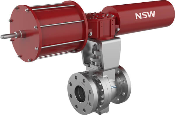
Inside the Safety Sentinel: Key SDV Valve Parts
Understanding the major components helps appreciate SDV design and maintenance:
1. Valve Body: The main pressure-containing housing, containing the internals. Material (carbon steel, stainless steel, alloy) is chosen for pressure, temperature, and fluid compatibility. Flanged or welded ends.
2. Bonnet: The cover assembly bolted to the body, providing access to internals and sealing the body. Often includes packing/stem sealing.
3. Trim: The internal components exposed to the process fluid that control flow:
* Seat: The sealing surface the closure member contacts.
* Closure Member: The part that moves to block flow (Ball, Gate, Disc, Plug).
* Stem: The shaft connecting the actuator to the closure member, transmitting force and motion. Critical sealing point.
4. Actuator: As discussed earlier (Pneumatic/Hydraulic spring-return or accumulator system). Mounts directly to the valve bonnet/yoke.
5. Positioner (Optional – for partial stroke testing): While SDVs are typically fully open/closed, some systems use partial stroke test (PST) positioners to verify movement without a full trip.
6. Solenoid Valves (Critical): Electrically controlled valves in the pneumatic/hydraulic supply line to the actuator. The SIS trip signal typically de-energizes these solenoids, causing rapid venting of actuator air/hydraulic fluid and allowing spring return.
7. Limit Switches: Provide electrical feedback to the SIS/control system confirming the valve’s position (Open/Closed/Tripped).
8. Local Position Indicator: A visual gauge (often on the actuator) showing valve position.
9. Yoke: The structure connecting the actuator to the valve body and supporting the stem.
10. Packing/Seals: Critical for preventing process fluid leakage along the stem and at body/bonnet joints. Materials must handle process conditions.
Speaking the Language: The SDV Valve Symbol
On engineering drawings, especially Piping and Instrumentation Diagrams (P&IDs), symbols quickly convey valve type and function. The SDV symbol combines elements:
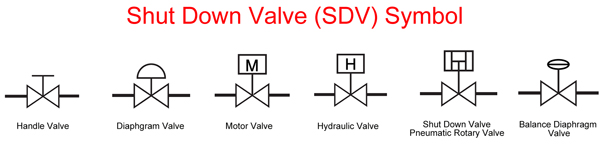
1. Base Valve Symbol: Represents the valve type:
* Ball Valve: Two triangles pointing inward, connected by a line.
* Gate Valve: A wedge shape between two vertical lines.
* Plug Valve: A diamond shape between two vertical lines.
2. Actuator Symbol: For SDVs, this is crucial:
* A square (representing a pneumatic/hydraulic actuator) is drawn attached to the valve symbol.
* Within or adjacent to the square, a small triangle pointing *towards* the valve indicates spring return.
* The direction the triangle points (towards the valve symbol) signifies the fail-safe action:
* Triangle pointing at valve = Fail Closed (FC)
* Triangle pointing away from valve = Fail Open (FO) (Less common for SDVs)
3. SIS Designation: Often labeled “SDV”, “ESDV”, “SSV”, or tagged with the specific SIF number (e.g., XV-101).
4. Solenoid Symbol: Sometimes a small circle with the letter “S” (for solenoid) is added near the actuator symbol.
Example Symbol (Fail-Closed SDV Ball Valve):
|——| <– Actuator (Square)
| > | <– Spring Return Triangle (pointing in = Fail Closed)
|——|
|
/—–\
—-| O |—- <– Ball Valve Symbol (Circles/Triangles)
\—–/
(Note: Actual P&ID symbols vary slightly by company standards, but the spring-return actuator is the key SDV/ESDV identifier).
Choosing the Right Tool: SDV Valve Types
The optimal valve type for an SDV application depends on several factors: required sealing integrity, speed, pressure drop, fluid characteristics, size, and cost. The most common types are:
1. Ball Valve SDVs:
* Operation: Quarter-turn (90-degree rotation). A ball with a bore rotates to open/close flow.
* Advantages: Very fast operation (ideal for SDV speed), excellent bubble-tight shutoff (essential for isolation), low torque requirement (good for actuator sizing), minimal pressure drop when open, full bore available, bi-directional sealing. Most common SDV type.
* Disadvantages: Not ideal for severe throttling (cavitation damage), potential for seat damage with slurries or solids.
* Best For: Most gas, liquid, and clean service applications requiring fast, tight shutoff. Wide range of sizes/pressures.
2. Gate Valve SDVs:
* Operation: Multi-turn linear motion. A wedge or parallel disc slides perpendicular to the flow path to open/close.
* Advantages: Straight-through flow, very low pressure drop when fully open, good for slurries/slightly dirty fluids (less seat damage risk than ball valves), bi-directional sealing possible.
* Disadvantages: Slower operation than ball valves (multi-turn vs quarter-turn), potential for seat/gate erosion in high-velocity flow when partially open, more prone to leakage over time compared to ball valves, requires more actuator thrust.
* Best For: Larger bore lines where pressure drop is critical, slurry services, applications where speed is less critical than in other parts of the system. Less common for modern SDVs than ball valves.
3. Plug Valve SDVs:
* Operation: Quarter-turn (90-degree rotation). A tapered or cylindrical plug with a port rotates within the body.
* Advantages: Simple design, reasonably fast, good bubble-tight shutoff potential, can handle slurries reasonably well, full port available.
* Disadvantages: Higher operating torque than ball valves (especially in larger sizes/severe service), potential for galling (metal-to-metal contact), lubrication requirements (for lubricated types).
* Best For: Moderate speed requirements, slurry services, smaller lines, specific applications where plug design is advantageous. Less common than ball valves.
Selection Considerations Summary
* Speed: Ball > Plug > Gate
* Shutoff Integrity: Ball ≈ Plug > Gate
* Pressure Drop (Open): Gate ≈ Ball (Full Port) ≈ Plug (Full Port) << Ball/Plug (Reduced Port)
* Slurry/Solid Handling: Gate > Plug > Ball
* Actuator Force/Torque: Gate (High Thrust) > Plug > Ball (Generally Lowest Torque)
* Cost (Generally): Ball ≈ Gate > Plug (Highly size/material dependent)
Conclusion: The Non-Negotiable Role of the SDV Valve
The Shutdown Valve (SDV or ESDV) is far more than just another valve in a pipeline. It is a meticulously engineered, rigorously tested, and critically certified safety component, serving as the ultimate mechanical safeguard within a Safety Instrumented System. Its ability to rapidly and reliably isolate hazardous fluid flow upon demand is fundamental to preventing catastrophic incidents in high-risk industries.
Understanding its meaning (Shutdown Valve), its fail-safe operation driven by specialized actuators (spring-return pneumatic/hydraulic), its clear distinction from control valves like MOVs, its relationship with BDVs, its standardized dimensions and parts, its unique P&ID symbol, and the various valve types (primarily ball, gate, plug) used in its construction is essential for engineers, operators, and safety professionals.
Selecting, installing, testing, and maintaining SDVs according to stringent international standards (like IEC 61511, API 6D, API 6A) is not just good practice; it’s a core requirement for operational integrity and the protection of people, plants, and the planet. The SDV valve truly stands as a silent, vigilant guardian, ready to act when safety demands it most.
Post time: May-30-2025